PDM16M

The module replaces conventional relays, fuses and circuit breakers to simplify wiring and switching requirements while increasing reliability.
Features
- Each output is protected against overcurrent, short circuit and thermal overload
- Outputs programmable in 1 A steps and controllable through a combination of switching inputs, CAN messages and logic functions
- Performs up to 200 logical operations and functions that can be used to selectively shut down systems
- Provides complete diagnostic information via CAN
Specifications
Entries
- x switching inputs: 0 to 51 V range, 0.2 V resolution
Exits
- 8 x 20A outputs: 20A continuous, 115A transient (typical)
- x 8A outputs: 8A continuous, 60A transient (typical)
Communications
- 1 x CAN
Voltage
- 30V max.
Ingress Protection (IP) rating
Physical
- Weight grams
Compatibility
MoTeC ECU Models
- M1 series (package dependent)
- Discontinued: M84, M400, M600, M800, M880
MoTeC Dash/Logger Models
- C125, C127, C1212, C185, C187, C1812, CDL3, L120, L180
- Discontinued: SDL, SDL3, ADL, ADL2, ADL3, ACL
Accessories
MoTeC UTC #61059(UTC is required, not compatible with MoTeC CAN cable).
Software
The latest software can be found in the downloads below.
PDM Manager software is used to:
- Configuring all inputs, outputs, CAN messages and conditions
- Monitoring all channel values
- Exit test
- Firmware update
Wiring
CAN Wiring
The PDM is connected to the CAN bus. Make sure the wiring complies with CAN requirements and that the CAN bus has at least a 100R termination resistor. More information can be found in the user manual located in the downloads belowTo communicate with the PC, a CAN connector must be connected to the CAN bus. To connect the PDM directly to the CAN connector, connect according to the following table.
PDM pin | PDM Name | CAN connector pin | CAN connector wire |
---|---|---|---|
CAN YOU | 4 | Green | |
CAN Hi | 5 | White | |
0 V | 1 | Black |
Wiring example
Wire gauge
Suitable wire sizes are 24# to 20# for 8A outputs and 20# to 16# for 20A outputs. Wire size should be chosen according to the current drawn by the connected device and to ensure that the voltage drop is acceptable. In the long run, it may be necessary to use a heavier gauge wire to minimize voltage drop. The wire size should also be compatible with the connector pin; using a smaller wire size than recommended may result in a poor crimp.
Dimension and Assembly
Measurements in mm.
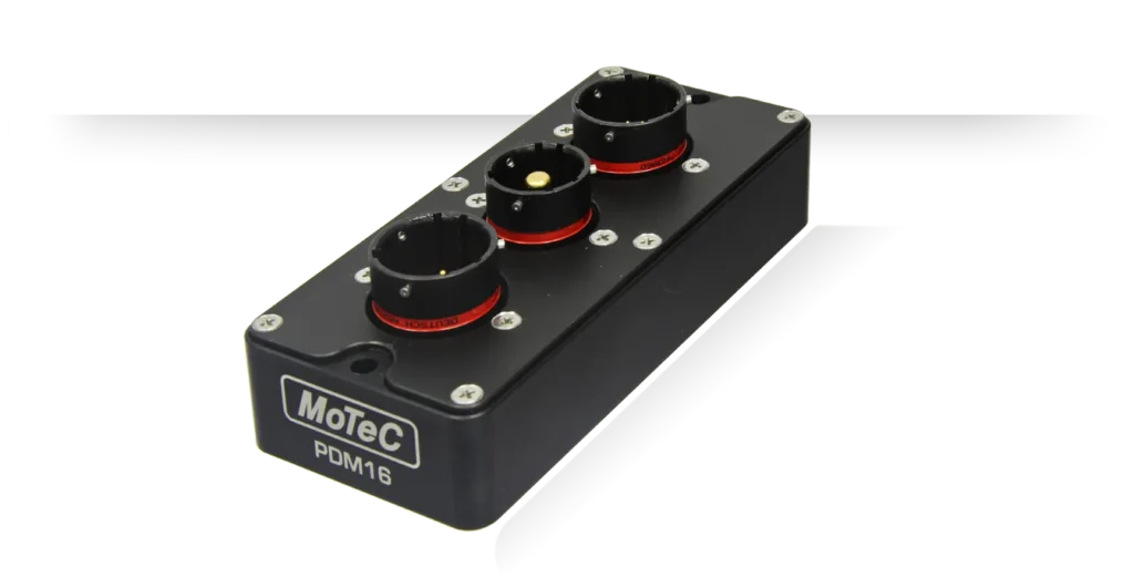
The product provides through holes for mounting. See drawing for details.
An assembly drawing or a surface CAD model is available upon request from MoTeC
Pinout
Connector A
26-pin Autosport connector
Mating connector #65040
Pin | Function |
---|---|
A_A | 8 Exit 9 |
A_B | 8 Exit 10 |
B.C | 8 Exit 11 |
A_D | Digital/Switched Input 1 |
A_E | Digital/Switched Input 2 |
A_F | Digital/switch input 3 |
A_G | 0 V |
A_H | 0 V |
A_J | CAN Low |
A_K | MAY High |
A_L | 8 Exit 12 |
A_M | 8 Exit 13 |
A_N | 8 Exit 14 |
A_P | 8 Exit 15 |
AIR | 8 Exit 16 |
TO THE | Digital/Switched Input 4 |
A_T | Digital/Switched Input 5 |
A_U | Digital/switched input 6 |
A_V | Digital/Switched Input 7 |
A_W | Digital/switched input 8 |
A_X | Digital/Switched Input 9 |
A_Y | Digital/switched input 10 |
A_Z | Digital input/switch 11 |
A_a | Digital/switched input 12 |
A_b | Batt– |
B.C | Batt– |
Connector B
1-pin waterproof connector
Mating connector:
#68093 (#6 AWG wire gauge)
#68094 (#4 AWG wire gauge)
Pin | Function |
---|---|
B_1 | Battery + |
Connector C
8-pin waterproof connector
Mating connector: # 68092 (Deutsch AS616-08SN)
Pin | Function |
---|---|
HERE | 20 Exit 1 |
C_B | 20 Exit 2 |
C_C | 20 Exit 3 |
CD | 20 Exit 4 |
C_E | 20 Exit 5 |
C_F | 20 Exit 6 |
C_G | 20 Exit 7 |
C_H | 20 Exit 8 |