- The paddles can be connected to any digital, universal digital or analog voltage input pin.
- Option for single input wiring, see: Paddle Wiring
- The pneumatic actuator can be connected directly to the ECU without the need for an external amplifier or relay. Two half-bridge injector outputs, peak hold or low side outputs can be used; one output for up shifts and one output for down shifts.
- The pneumatic pump is controlled by the M1. It can be powered from a MoTeC PDM using CAN or a direct wired high current relay using a Half Bridge, Peak Hold Injector or Low Side output.
- The tank pressure sensor can be connected to any analog voltage input.
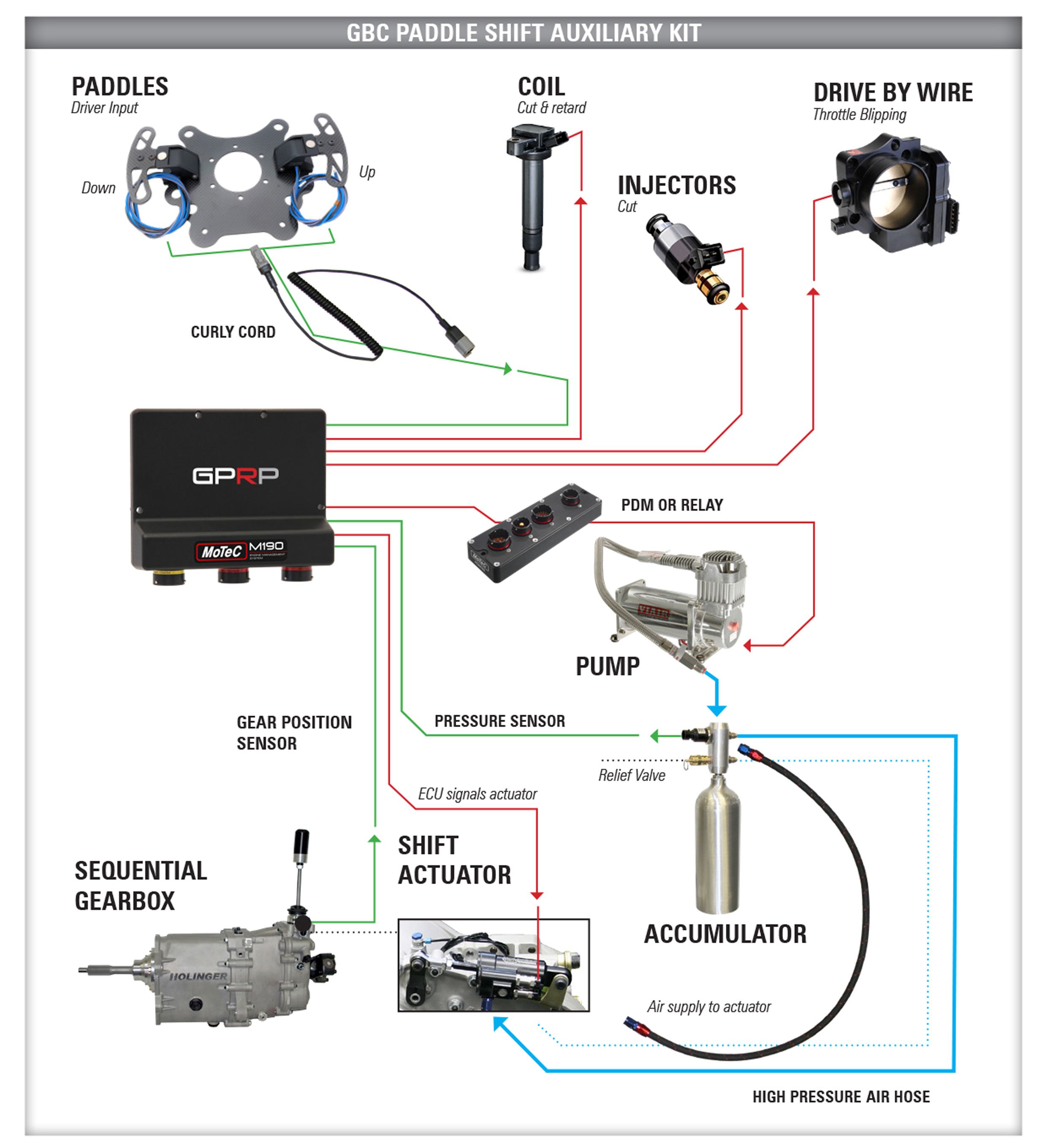
Paddle shift sequence:
- The order to start a shift comes from the driver's paddle.
- The system cuts or flashes the engine through the injectors, coils or Drive by Wire.
- The shift actuator moves the gearbox between gears.
- When the next gear is reached, power is reintroduced.
It is recommended that the paddles are mounted to the supplied plate attached to the rear of the steering wheel using two M4x0.7 countersunk screws per paddle with a retaining compound (e.g. Loctite 222). The mounting screws should be no more than 4mm longer than the thickness of the mounting plate. Typically 6mm long screws would be used with the supplied 2.5mm thick mounting plate.
Mounting hole dimensions are shown below. Also shown are alternative handle mounting holes that offset the paddle handle outward by 6mm on each side.
Dimensions in mm
Mounting plate
Dimensions in mm
The blades are supplied with 500mm unterminated 18AWG flying leads for freedom of configuration. Circuit descriptions are as follows:
| Color | To use |
| Blue | Normally open contact |
| Gray | Normally closed contact |
| Black | Common |
Typically the blue wires will be connected to a digital or switching input from a controller (e.g. Engine Management System) and the black wires will be connected to 0V/ground; there will be no connection to the gray wire.
Alternative Connection – Single ECU Input
This method allows both paddles to be connected to a single input when supported by the controller.
The resulting behavior of Vout is as follows:
| Action | Vout |
| Off | 2.500 |
| On top | 0.596 |
| Below | 4.037 |
| Both | 1.811 |